The birth of a vehicle
If you have been following my development blog you know that I am working on Project Slide, a vehicle action game. Given that the game is all about vehicles, you might think I would have started by creating a bunch of interesting and fun vehicles to put into the game. You would be wrong. In fact, for the first 6 months so of development there was only a single test car to play around with. Later a heavy hauler as well as a few different trailers were added to the game, but they were all minimum-effort creations, just enough to be able to flesh out the gameplay mechanics and code.
I am making the game mostly as a solo-developer, and so far I have had my hands full with programming and design tasks. Many of the 3D models (eg. rocks, trees etc.) have been ready-made assets, bought from asset stores. I have done a little 3D modeling though, enough to scribble together the occasional vehicle or exploding barrel but nothing substantial. The plan has been for me to create rough versions of objects and create the gameplay around those. A proper artist could then take the rough versions and create interesting and fully fleshed-out versions of them for the final game.
However, lately I have found the idea of creating objects myself more and more intriguing. That doesn’t mean I am going to model everything myself. I am sure I’ll use lots of ready-made assets as well as get an artist to help out with certain tasks (such as 2D art), but I find it very liberating to have the skills to create an object myself.
In this blog post, we’ll look at the first large and complex object I have made for Project Slide; a new vehicle. And not just any new vehicle, but the first properly designed vehicle with a place in the in-game lore as well as the gameplay systems. This is not going to be just about the art and visual design. We’ll look at some technical systems I had to write for the vehicle as well.
Dude, where’s my vehicle?
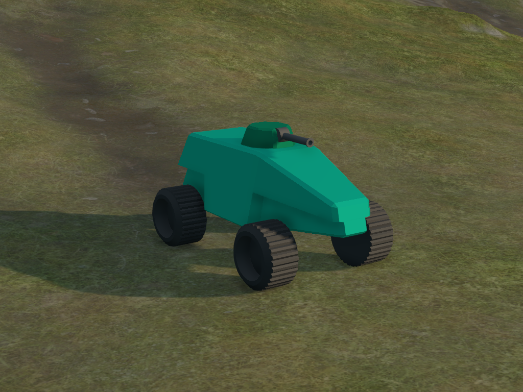
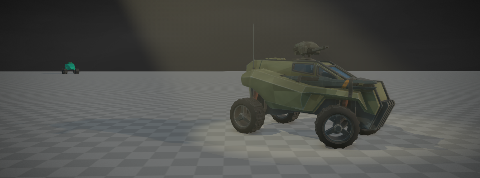
First, let’s look at what we had before. Behold! The old workhorse, the venerable “Car1” as it is called (see image 1). If you have read any of my previous blog posts you might have seen this weird box mysteriously floating near four black bottle caps.
There are a few versions of this car. There is a blue one which has a behavior tree AI brain (detailed in the AI blog post series), and there used to be an orange one which had an older version of the AI system. Regardless of version and color, it is a nimble scout vehicle with a rotating gatling gun turret on the roof. It is used as an attack vehicle as well as for reconnaissance and exploration. It can’t haul cargo but it can be used to protect heavier hauling vehicles from enemies.
This kind of vehicle will be useful for many gameplay situations and missions. It works well for combat scenarios as well as for traveling between areas and exploring the world. It is also fun to drive and quite fast. It would work well as the starting vehicle in the campaign. Finally, it is a good vehicle to use when developing gameplay features and experimenting. It was only natural to take Car1 and develop it further.
Click on the images for larger versions.
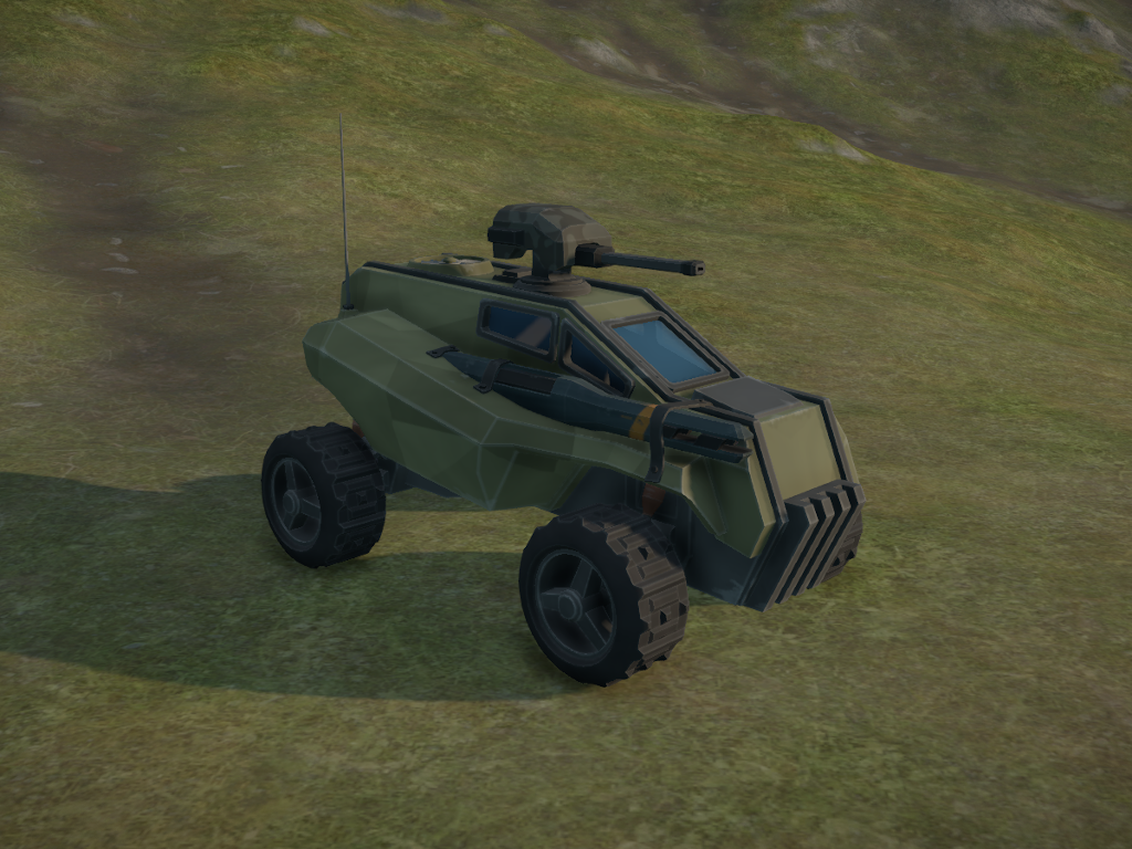
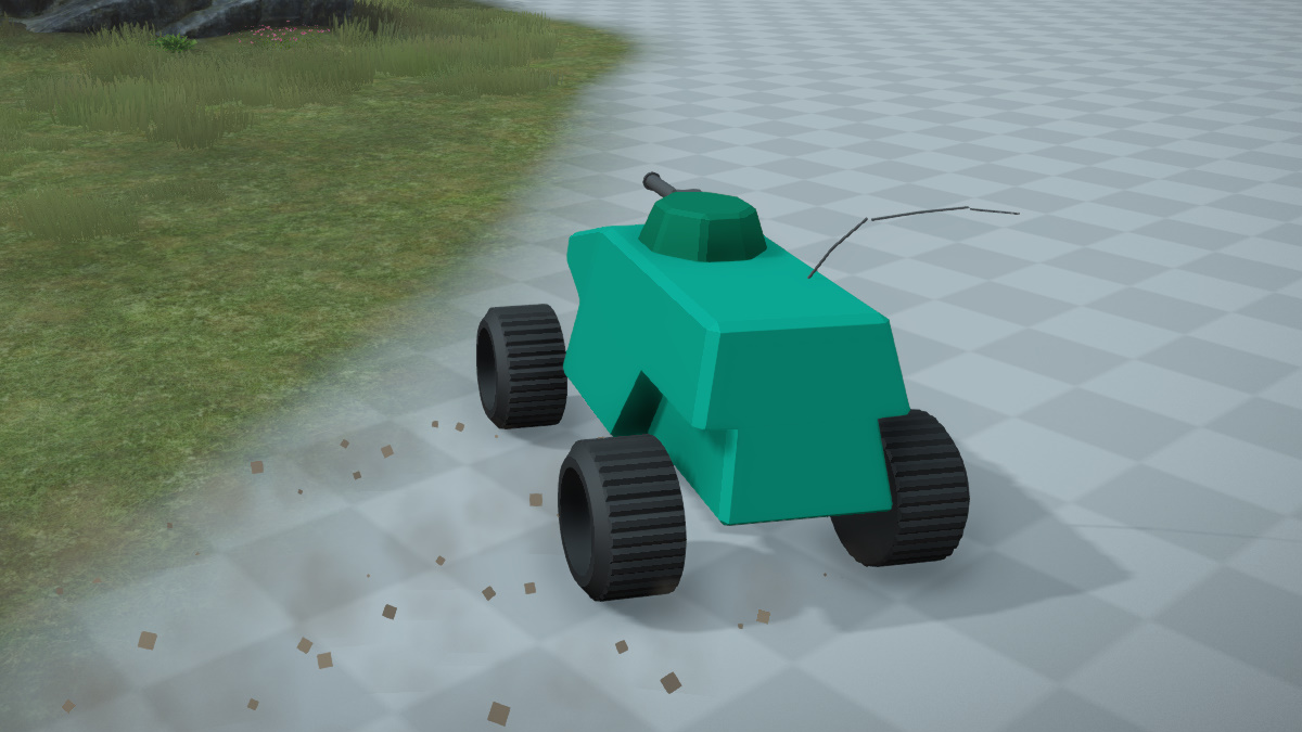
On the left (image 2) you see the new version of the vehicle, imaginatively named “Car2”. I haven’t decided on a proper in-universe name yet but I have a few ideas. Starting with Car1, it took me about three weeks to reach this version of the vehicle and I am quite happy with the results so far.
A large part of the time was spent learning how to use Blender, especially with regards to materials and texturing, so the next vehicle should be faster to make. Car2 cannot be considered “final” in its current state. Things like audio and particle effects were untouched and both still need a lot of work.
Developing it this far makes a big difference though. I also became much more confident in my abilities to create assets, I came up with a few new ideas for gameplay features, and I got to solve some interesting math problems in the process. Oh, and I discovered (and fixed) a bunch of bugs in my tools and the game engine. Nothing like dogfooding your software!
Let’s look at the whole development process, which pieces and systems make up the vehicle and how I tackled them. First though, here is a video showing the vehicle in action. Dont mind the half-empty test level.
The concept phase
At a typical game studio, when work starts on creating a vehicle or similar object it is common to have a concept artist create a few ideas about what the vehicle should look like. I don’t have that luxury at the moment, but luckily there are lots of really cool concept art pieces on the internet. I started by browsing Pinterest’s suggestions for sci-fi vehicles and made notes of things I liked. This allowed me to create my own “concept art” piece to base my 3D modeling on. I didn’t make a 2D concept art piece in the traditional sense though, since I am completely useless at 2D art. Instead I put together a “blockout” model in Blender.
3D Blockout
A recurring problem I have when modeling is that I tend to get stuck on technical details when I should be concentrating on the big picture. Any good modeling tutorial will tell you that you should aim to keep a clean quad-based topology, that you should avoid lots of intersecting geometry etc. For someone relatively inexperienced with modeling tools (such as myself) it is easy to get stuck trying to fix these problems when you should let your creative juices flow.
To help with these issues I have adopted a workflow where I model non-trivial objects twice. First, I create a very rough version of the object (usually with lots of technical issues) to get a feel for the shape, size and scale of the object. I don’t spend any time on materials or texturing at this point, and I typically don’t export it from the modeling tool into the game engine, since it is important to keep this phase quick. If you are unsatisfied with the results you just scrap the blockout and make a new one. This allows you to quickly try out lots of different ideas without getting bogged down with details.
For Car2, the concepting and blockout phase took about a day and at the end I had this in Blender:
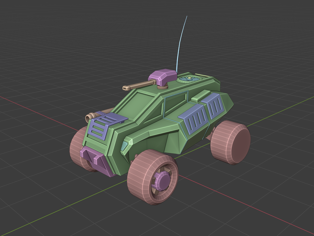
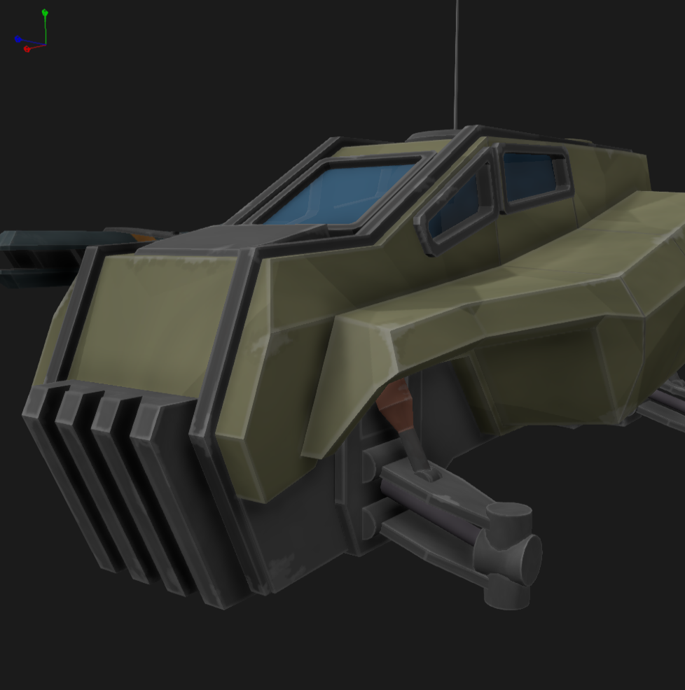
When creating an object of any sort, it sometimes helps by imagining the story of the object. For Car2, I imagined a scout vehicle that resistance fighters have retrofitted with armor and weapons to make it combat capable. That is why the chassis-mounted gun barrel is fastened with a metal strap bolted onto the front of the vehicle.
As you can see from the blockout image, it is quite hastily put together. The wheels are a bit different, and some of them are missing pieces (because I tried something out and then deleted or hid it). Blender’s random color render mode is great to quickly differentiate between the different pieces and gives the model a bit more life compared to a single color.
Here are some of my design principles/ideas for this vehicle:
- For the chassis I went for a blocky, functional design with few smooth curves. The vehicle is supposed to belong to the resistance fighters, a group of people who have to make due with what they have. The body has been reinforced with a steel frame, running along the chassis from front to rear. Additional armor plating has been bolted onto the chassis on all sides.
- Asymmetry along the X axis (ie. between the right and left sides of the vehicle). I didn’t want the vehicle to look like it was mirrored in the modeling tool. The chassis mounted gun, the exhaust pipes and the antenna help with breaking up the symmetry. For the final model, I took it further with the camouflage paint as well as some details on the turret.
- I wanted to have moving parts on the vehicle. The old Car1 model feels very lifeless and I wanted to add life to the vehicle even though technically it isn’t alive. I added a spinning turbine onto the roof and an antenna which reacts to the movements of the vehicle. The spokes on the wheels are also emphasized to make it easy to see the rate at which the wheels spin.
- On the physics side the vehicle has a sophisticated suspension model, thanks to the PhysX vehicle SDK, complete with spring and damping forces, camber angles, adjustable droop and extension ranges etc. I want to make sure that the suspension looks as nice as it feels when driving the vehicle over uneven terrain, so I made sure the suspension arms and springs are clearly visible, especially at the rear where the camera is pointed most of the time.
- I wanted things that can be removed from the vehicle without having to modify the underlying mesh. This can be used to signal how much damage the vehicle has taken, and allows for nice looking damage effects. The armor plates can be damaged and fall off. Suspensions can be damaged making wheels fall off etc.
Do note the highlighted edges on the blockout models in Blender. This is especially visible on the wheels. They are completely single-colored but an option for the “cavity rendering” in the Blender viewport makes the edges brighter than the faces. This will become relevant later.
Final 3D model
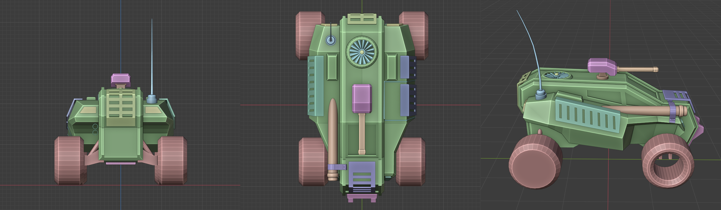
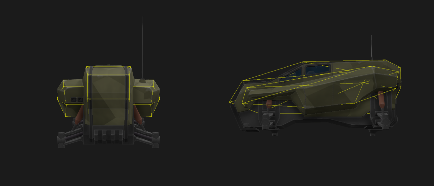
When I was happy with the blockout model I started working on the actual 3D models of the vehicle. To make the process easier I captured screenshots of the blockout along all 3D axes and added them as images in Blender, when modeling the final chassis.
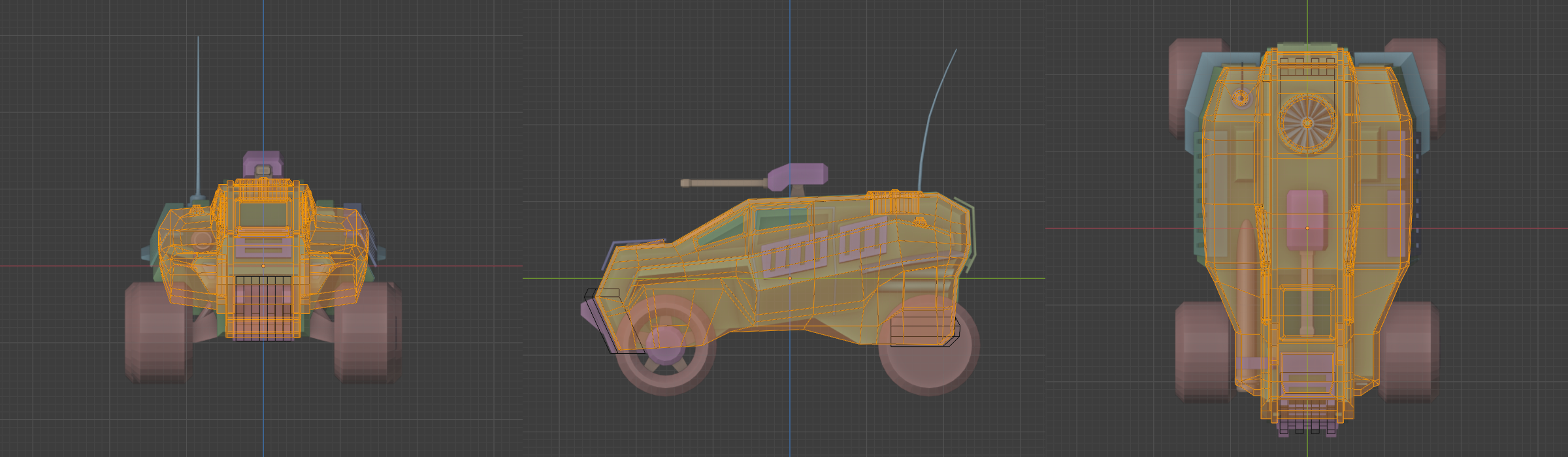
As you can see from the images below the final chassis shape (yellow wireframe overlay) matches the blockout pretty closely.
The vehicle consists of a number of separate mesh objects. This allows for creating alternate versions of the vehicle, eg. one which hasn’t been retrofitted for combat. All moving pieces were also created as separate meshes so that they can be plugged into the gameplay code which moves them around in the local space of the vehicle object.
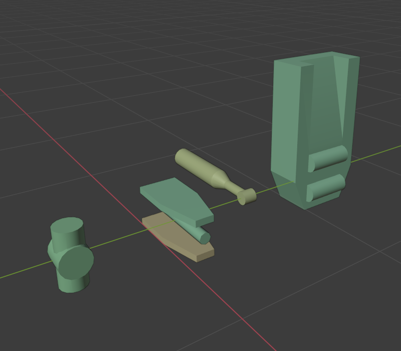
The image on the left shows all pieces of the wheel suspension assembly. From left to right: wheel knuckle, upper control arm, axle, lower control arm, spring and suspension fixture. These pieces are then put together in the game engine’s object type editor. The antenna is a dynamic mesh which follows the movement of the physics objects and is completely created in code.
While creating the final 3D models I came up with new ideas for many of the vehicle’s parts. The chassis mounted gun in the blockout is represented by a long boring cylinder. In the final version it is a railgun, which looks much nicer in my opinion. Having the cylinder in the blockout helped a lot though, since it was always clear how big the weapon was going to be. I decided that the railgun should be fastened by metal straps at multiple places, to reinforce the idea that the gun is retrofitted onto the vehicle, rather than being an original installation. I used a slightly different texture for the roof-mounted gun turret for the same reason. At one point I had a gun turret model with a much rounder, more aerodynamic shape. It looked very out-of-place on the roof of the vehicle, though, so I decided to distinguish it using a texture instead.
The most observant of you might have noticed that the armor plates found on the blockout model are missing from the final model. The destruction system is still incomplete so they wouldn’t work yet, and they can always be added later. Also, I was quite happy with how the railgun turned out so I didn’t want to cover it up with armor at this point. The front of the vehicle looks a little empty without armor, however, so I need to do address that somehow.
Materials and textures
The material and texturing phase was the one I was most nervous about when I started working on the vehicle. I have done a little 3D modeling over the years, but no texturing or material design. Also, I had no experience with how Blender handles materials so there was a lot to learn. With that in mind, I think the vehicle materials and textures turned out pretty good. All textures are created in Blender with the exception of a few labels I made in GIMP and brought into Blender later.
Remember those highlighted edges in Blender I talked about earlier? I liked how the model looked with the “cavity rendering” turned on, so I tried emulating the effect by hand-painting edge highlights onto the texture. The result can be seen in the image on the right. The highlighted edges give the model an almost comicbook-style look which I like. The highlight strength and thickness is a bit inconsistent across the vehicle but as a first attempt I think it looks very nice.
I should mention that I use a very basic lighting model for the game. The vehicle materials only use a diffuse texture, color values for diffuse, ambient and specular light + a specular highlight power value. The engine also supports normal and specular maps, but I think it works quite well even without them. Also, since I model directly in low-poly there aren’t any high-poly models to generate normal maps from. I might add normal maps later if I find the diffuse-only model isn’t flexible enough for my needs. Some objects in the game, eg. rocks and cliffs, already use normal maps.
Let’s look a bit closer at how the most complex texture, the chassis texture, is created in Blender. The image below shows the Blender shader node graph for the chassis material. The material is baked into a single texture which is loaded into the game engine. The material uses a mix of procedural and hand-drawn textures. Each dark box in the image adds a certain feature or detail to the final texture. We start at the top-left by generating the camouflage pattern. This is done using a couple of voronoi textures. We then construct the green-brown base color as well as the gray color used on the bottom half of the chassis. These two are applied to different parts of the chassis by looking up the correct faces in a “placement texture”. This way I can mark a face as beloning to the bottom part, and it will get the correct base color.
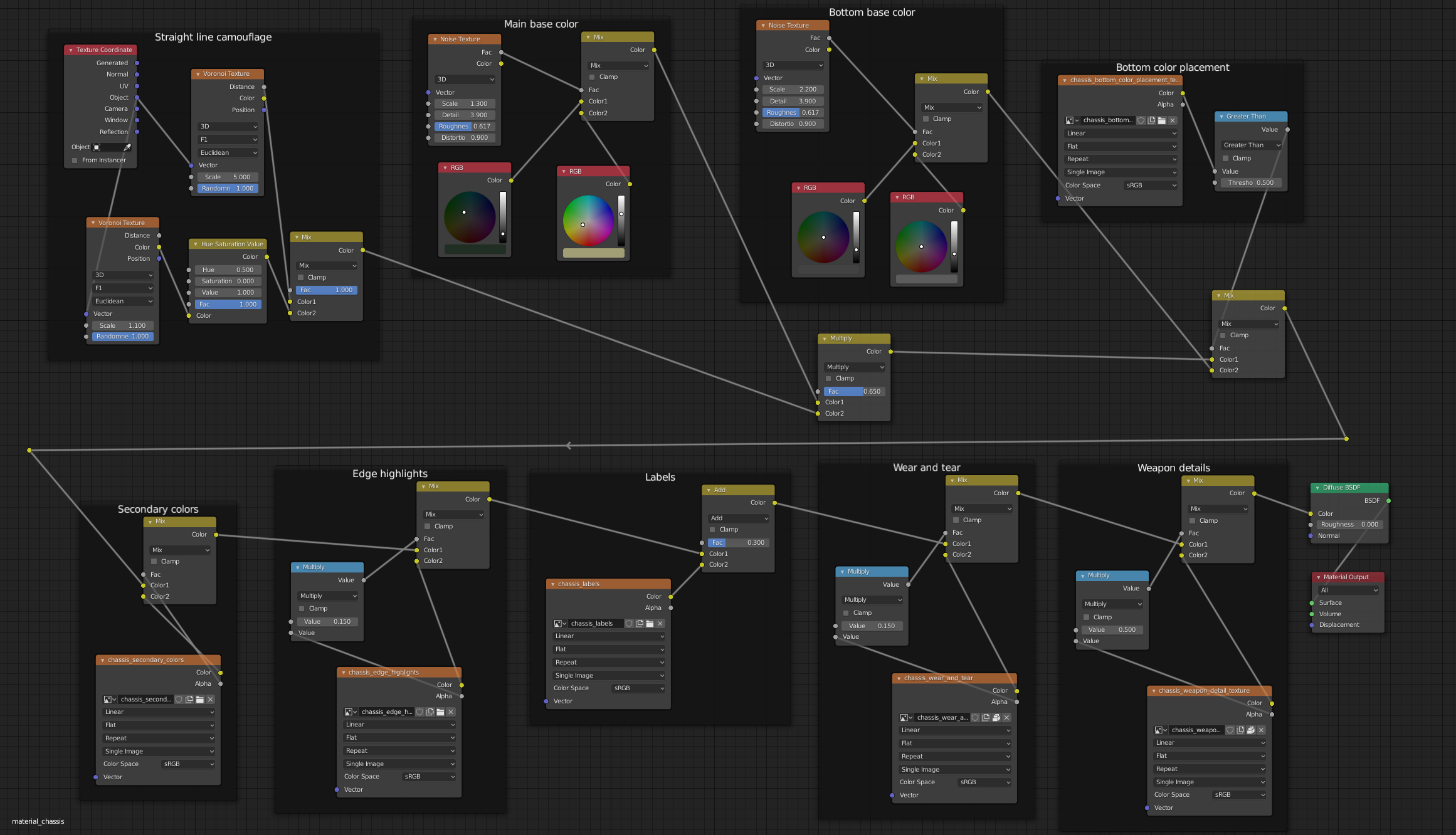
We now move to the bottom row in the shader graph. Every dark box on this row represents a texture which adds some details to the material. All of these textures are hand-painted in Blender (except the Labels texture, as previously mentioned). It works similarily to layers in Photoshop or GIMP. First, we color certain parts of the chassis with a secondary color, then we add edge highlights etc. This allows for non-destructive editing of the material. You can skip certain parts of the pipeline to generate a different version. Eg. all details related to the weapons are applied in the last step. If I want to have a version of the vehicle without the weapons I can simply skip that step and Blender will leave out the weapon details, such as the darker areas near the railgun’s muzzle.
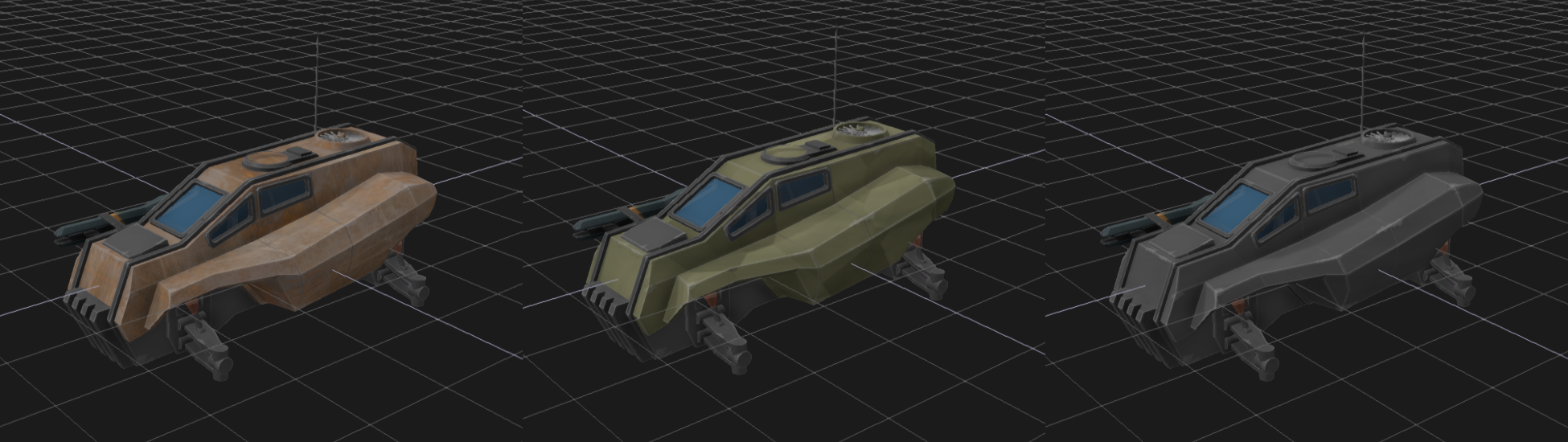
You can also generate variants of the same vehicle by replacing the base color. Below you can see a couple of quick tests I made where the camouflage base color is replaced with something else. In the left image I replaced the base color with a rusted metal texture. The UV mapping isn’t quite right but it serves as a quick test. In the right image the whole chassis is colored with the bottom part base color. Note how the edge highlights, scratches and other details are still present in all versions since those layers were untouched.
Windshields
The windshields (or windscreens, or… windows) of the vehicle were a bit trickier than I anticipated. I started by having them completely opaque, coloring them dark blue and painting some dirt onto the edges, but that didn’t look convincing. After that I experimented with rendering a cube map at the position of the vehicle and using it to render fake reflections onto the windshields. This sort of worked, but the effect was very subtle and hard to see (mainly because the windshields are fairly small). Also, the reflections were only convincing if I kept rendering the cube map to update the reflections each frame, and that would have been too slow in a scene with 10 or so vehicles.
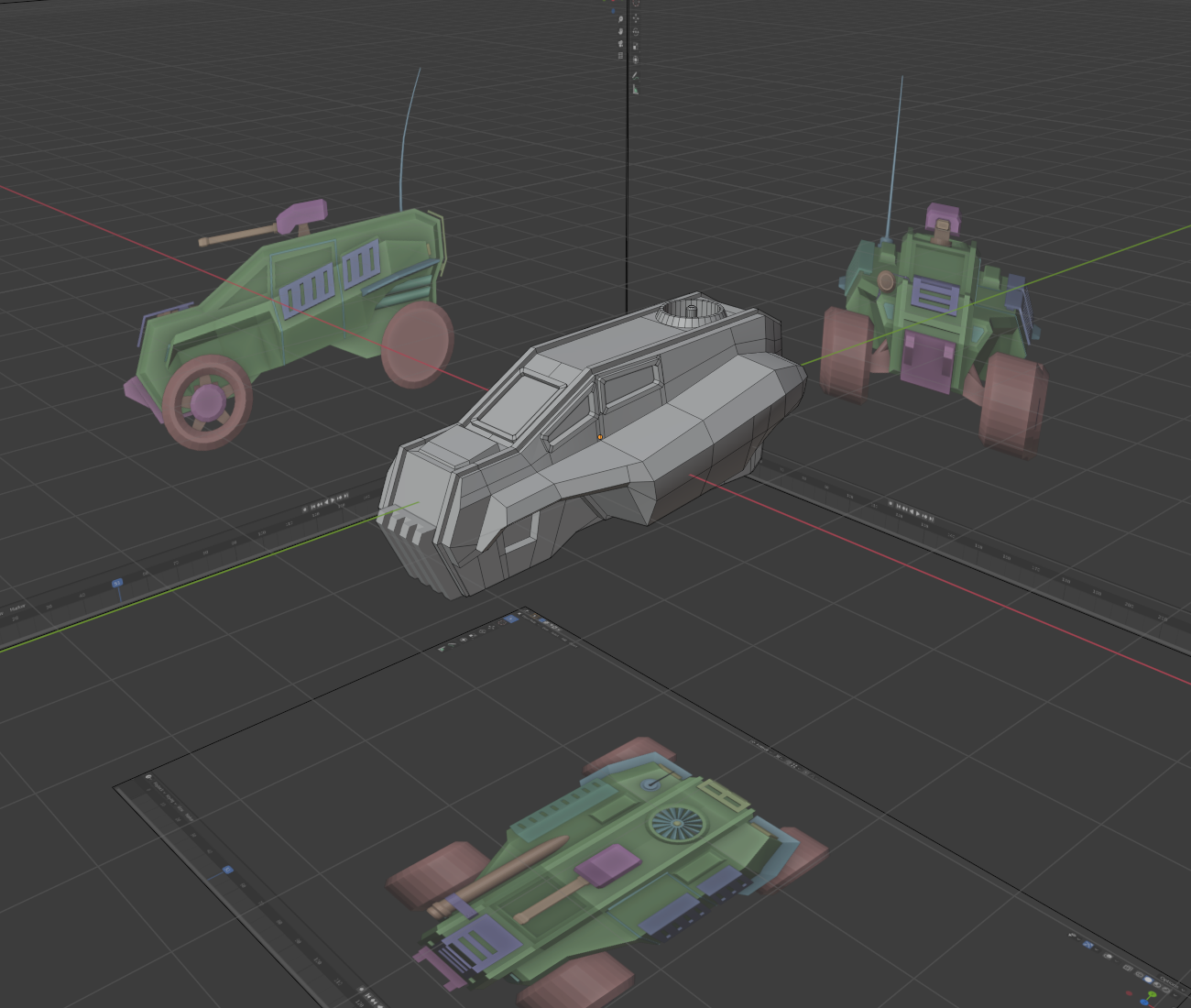
Finally I decided to go with transparent windshields. I tinted them blue and gave them strong specular reflectivity which makes them reflect the sun, for example. This did look nice and was a lot cheaper, performance-wise, than the cube map reflections. It posed a new problem though, as suddenly you could see inside the vehicle. Up until this point, I had never planned to model an interior at all but now I needed one. You can see the low-poly interior model on the left in the image below.
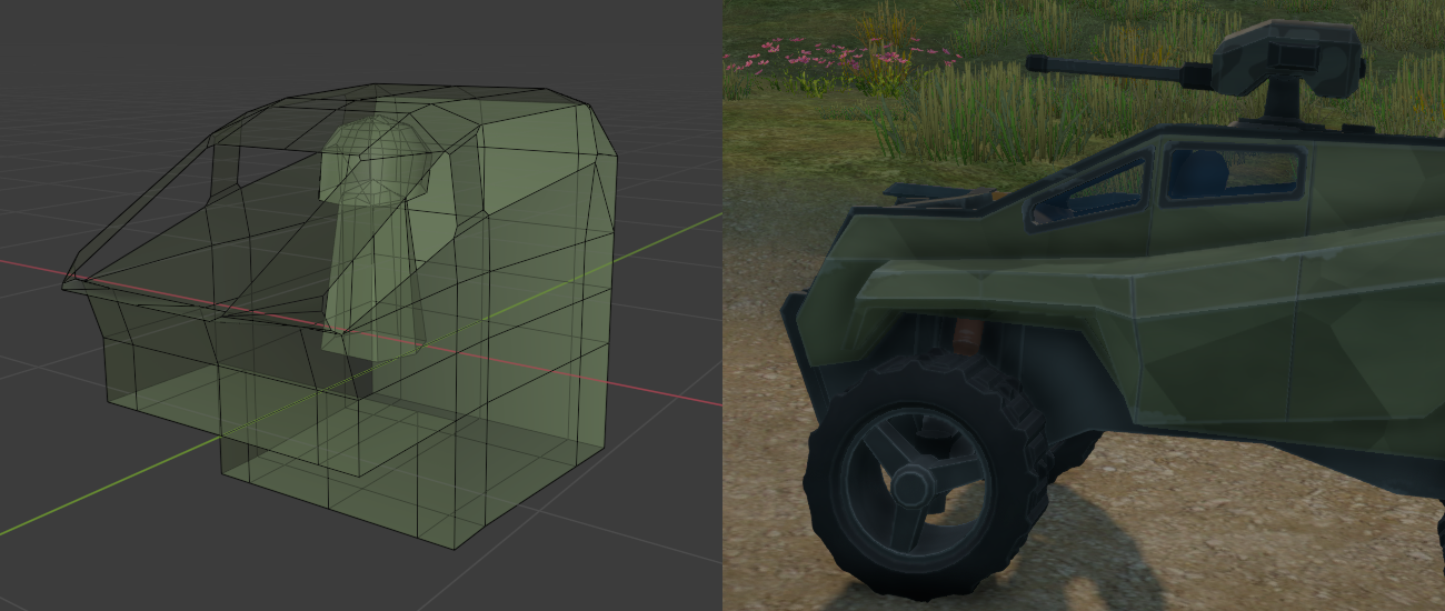
In some games you can clearly see that the driver’s seat is empty which I have always found a bit silly. To prevent this I modeled a quick “driver” as part of the interior. The whole thing is rendered with a single dark, almost black, color. The intent is to give the illusion that there is an interior but not let it steal the focus of the player. On the right you can see how the driver’s silouette is nicely visible through the windshields.
Physical characteristics
So far we have only talked about the graphical side of things. What about the physical characteristics of the vehicle? What kind of engine does it have? What is the top speed? etc. Before I go into any details, keep in mind that the vehicle has been tuned for fun gameplay, not an accurate physical simulation, so some of these may be weird or unrealistic. Even though the game takes place in the future this vehicle uses a traditional combustion engine.
- Max torque provided by the engine: 600 Newton-meters.
- Max RPM: About 3800.
- The torque and RPM above results in a horsepower of around 320.
- Four-wheel drive, limited-slip differential.
- Automatic gearbox, 5-speed + neutral + reverse.
- Chassis mass: 1500 kg.
- Wheel radius: 60 cm.
- Wheel mass: 20 kg.
- Top speed: About 160 km/h (This will be lowered in the final game).
It is worth noting that the physical characteristics were largely unchanged between Car1 and Car2. For Car2 the wheels are offset a bit differently than for Car1, the rear wheels are a little further apart than the front wheels (as can be seen from the images above) and the chassis collision volumes are obviously different, but otherwise the cars are exactly the same. Tuning the physics of a vehicle is a time-consuming process and it is one reason why I wanted to base the vehicle on Car1 since it has felt nice to drive for a long time.
Most of the physics are handled by the PhysX vehicle SDK, so I won’t go into much detail about that here. However, recently I rewrote the automatic gear shift logic for the game. The PhysX vehicle SDK comes with a basic automatic gear box, but I found it too limited for my use. It looks at engine rotation threshold values and decides to shift up/down based on those. It also shifts one gear at a time, which means that shifting from fifth gear down to first (eg. after a sudden stop) takes a long time.
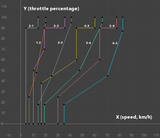
I wrote my own autobox implementation which uses a 2D plane to set a target gear based on throttle percentage and the current speed of the vehicle. The image on the left shows the shift curves used for the new vehicle. The system starts by creating a 2D point using the current throttle (Y-axis) and speed (X-axis). It then figures out which curves are closest to the point, to the left/right. If the point crosses a shift-up curve from left to right, it shifts up one gear. If the point crosses a shift-down curve from right to left, it shifts down a gear. If the point moves across many curves it can immediately jump to the correct gear instead of shifting one at a time.
This kind of system lets you do some interesting things. Consider a real-world car with an automatic gearbox. If you suddenly accelerate the car might temporarily switch to a lower gear to facilitate faster acceleration, before switching up again. This behavior is possible with the new autobox.
Let’s take an example. Say you are cruising at a fairly slow speed, just below 30 km/h with no (or very little) throttle applied. That would place the 2D point at the left side of the second-to-last-curve, ie. the 5-4 shift-down curve, close to the 0 throttle line. You would be in fourth gear. If you suddenly apply full throttle the point jumps straight up to the top of the graph putting it on the left side of the 3-2 shift-down curve. This shifts the gear down from fourth to second. As the speed increases, the point starts moving to the right. If you keep the throttle at maximum, sooner or later it will cross the 2-3 shift-up curve, putting you in third gear, then fourth and so on. Note that if you let go of the thottle after the inital acceleration, the shift-up will happen sooner due to the angle of the 2-3 shift-up curve.
Collision volumes
The chassis collision volume of Car1 is represented by a convex hull. However, the chassis of Car2 is not convex. Luckily it can be approximated by using two intersecting convex hulls; one tall and narrow, and another low and wide.
As can be seen from the image above on the right, the convex hull doesn’t cover the whole underside of the vehicle, ending about 50cm above the lowest point of the vehicle chassis. This is to prevent the chassis from hitting the ground when landing from a high jump, as well as to make it easier to drive over uneven terrain. On the top side, the collision volumes follow the visual geometry quite closely.
We want to make sure that collisions with other objects look correct. However, for simplicity only the chassis, wheels and antenna have collision shapes. The gun turret and railgun currently don’t collide with anything. Adding these is very simple, but I want to see if they really are needed before making the physics setup more complicated. The chassis’ center of mass is adjusted to be one world unit (ie. one meter) below the center of the object. This is to make it more stable when cornering at high speeds.
Animated parts
Let’s talk a little about the animated parts of the vehicle. They are, in rising level of complexity, the turbine on the roof, the suspension and the antenna. (I am leaving the actual wheels out of this discussion, since they have been animated since forever and the transforms are handed to you by the physics engine.)
The turbine on the root is the simplest one since it just spins. Just slap a RotatorComponent onto the vehicle, point it at the turbine mesh, and Bob’s your proverbial uncle. In the future though, I might want to have the turbine rotate only when the vehicle is in use, ie. driven by a player or an AI. This whole system is still missing, so currently it always spins.
The suspension was a little trickier to implement. I wanted the springs and control arms to move along with the wheels. However, I needed to tweak the placement of the wheels many times so that they looked nice with the chassis, felt nice to drive and didn’t intersect any geometry. Because of this it was unclear to me exactly how long the arms and springs should be.
In the end I wrote a system where the spring and control arms conceptually are attached to the wheel rather than the chassis. They then have a target position they “aim” at, somewhere inside the chassis. This way the dimensions of the whole wheel assembly could be changed and the arms would still point in the right direction. It does mean that both the springs and control arms intersect the chassis geometry quite a lot, but that doesn’t matter since it is never seen. Check out the video below where only the wheel assemblies are rendered.
You can see the spring meshes get pushed further into the chassis as the suspension is compressed. I am quite happy with the results, and the same code should be usable for many different vehicles as long as they have two control arms per wheel where one sits on top of the other.
Finally there’s the antenna, which turned out to be the most complex piece of the whole vehicle. For the longest time, I have wanted to add this kind of springy, elastic, antenna to the game and this vehicle work seemed like a good opportunity to make one.
I started by adding a few small and light rigid bodies on top of each other. These act as segments of the antenna. Each segment is attached to the next one with a spring joint and the bottom one is obviously attached to the chassis.
The result can be seen in the image on the right. It was a bit tricky to tune the joint spring/damping values and make them play nice with the segment size and mass, but after about a day I had an antenna which moved how I imagined it would.
Next up was rendering and it turned out to be the tricky part. I thought I could simply generate a cylinder mesh for each segment and move it around based on the transforms the physics engine gave me, but that didn’t look good.
Something I didn’t consider was that the rigid bodies in such a system don’t stay perfectly attached to each other all the time. They get pulled away from each other, they get squished together and they correct themselves over several physics updates. That means that rendering the antenna based on their transforms often resulted in broken geometry, weird angles and such things.
In the image below you can see me testing out the system (at the time, using Car1). The antenna segments are clearly visible and some of them aren’t event attached to each other. I wasn’t even doing any especially crazy moves at the time. This clearly wasn’t the way to render an elastic, springy antenna.
The solution I came up with was to take the segment positions given to me by the physics engine and generate a bezier curve path which runs through each position, in order. I then sample that path and expand the mesh into a dynamic “tube” representing the antenna.
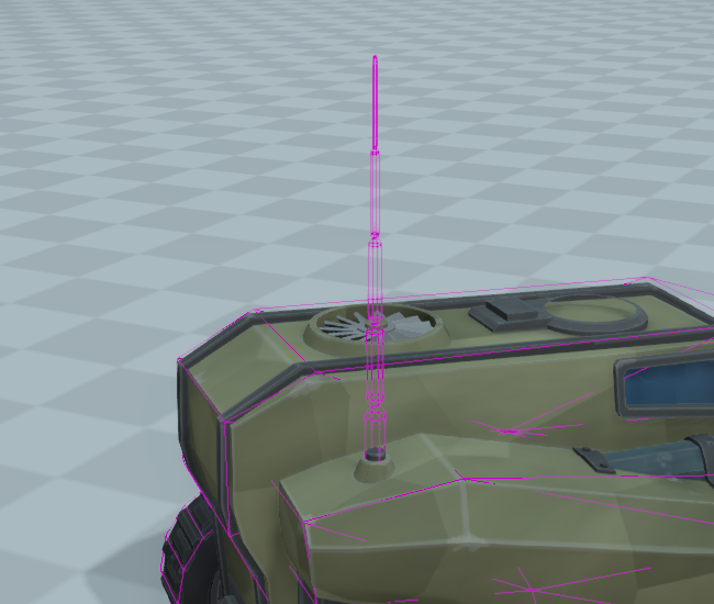
Take a look at the image on the left below. The pink parts are the physics segments we saw earlier. The yellow line is the bezier path generated from the positions of the physics segments. (They are not sitting on top of each other in the image since the bezier curve uses render interpolation while the physics visualization doesn’t). Finally the antenna geometry itself is the wireframe mesh. For this image I made it extremely thick to make it easier to see how the geometry is built. As you can see, the geometry closely follows the generated bezier path.
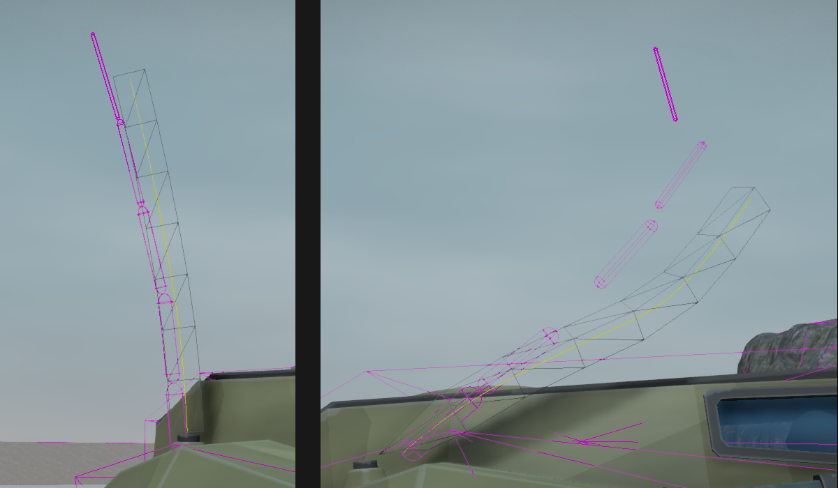
This works well since the bezier path is continuous even when the physics segments are detached from each other. The image on the right above shows the frame right after driving into a wall at high speed. The physics engine has not had time to correct the positions of the physics segments, but the generated bezier path is nice and smooth, resulting in a nice looking antenna. The whole thing has come off its fixture, sure, but it will be back there in an update or two…
I think the antenna turned out pretty nice. It is a small touch, but it really makes the vehicle feel more “alive” than before. Above is a video showing antenna movement and collisions. Halfway through the video the physics visualization is turned on so you can see the physics segments. The stiffness of the antenna is turned down in the video to highlight the movement. I think that is a little too wiggly for in-game use.
Future work
So after all this, what is left to do? As it turns out, quite a lot. I need to put in the final audio for the engine, add particle systems (such as exhaust pipe smoke), implement the railgun (VFX, audio, gameplay etc.), the AI needs to be taught how to drive this particular car, the damageable armor plats need to be added, etc. etc. Oh, and I need to decide on the final name for the car.
After spending a long time doing mostly programming, this has been really fun to work on. The first playable demo of the game will be focused on combat, and for that I need two vehicle types. I have already started planning the next car, and I have some ideas for how to make it very different than this one. Keep an eye on the blog for updates on that!