Creating a material editor for a custom game engine
While developing the material editor I kept a video devlog on Youtube where I went through the new features as I was developing them. Check out the playlist to see the material editor coming together!
Background
As a (mostly) solo developer using my own game engine I am used to working with less-than-stellar tools. In fact, there is a long TODO list of tasks for making the level editor and asset browser nicer and easier to use. Some of those will eventually get done, others won’t. There is only so much time in the day and you have to ship the game at some point.
When I implement a system in the engine I usually start with the runtime and make sure it works how I want. If the system requires some kind of data I typically author that data by hand using a human-readable format, such as JSON. Later on, if I feel I would benefit from a dedicated editor I might make one, but using a human-readable format is nice since you can put off spending time on an editor until you are sure you need one.
A good example of a system like this is the material framework in the Basis game engine. For the longest time I have edited materials using a text editor. I use on Visual Studio Code since it offers extensions allowing me to visualize colors and pick them using a color dialog instead of having to input everything as text. See image 1 below for an example of a material in VSCode.
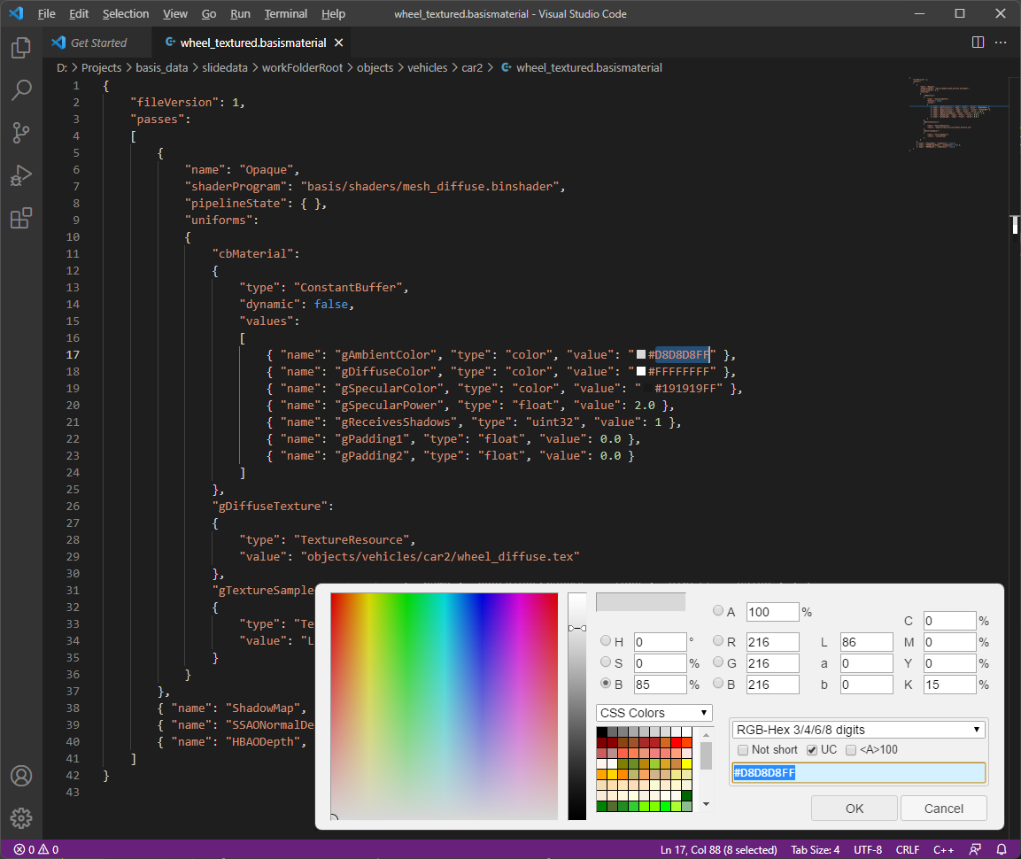
Not very user friendly, huh? The fact that materials can be reloaded/updated on the fly makes things a bit better. You only have to save the text file and wait a second or two and the changes show up in the running game/editor. But still, writing materials like this is hardly fun. You can easily break the JSON formatting and you have to remember a bunch of strings such as “ConstantBuffer” and “TextureResource”. Or was it “texture_resource”? Hmm…
Another problem with the system is that material data and shaders are kept in separate files. See that line in image 1 that starts with “shaderProgram”? That line specifies that the Opaque pass of the material uses the shader found at the resource path “basis/shaders/mesh_diffuse.binshader”. If you want to see what that shader looks like you’ll have to open up the source for the shader and look around. Now, let’s say that for this particular material, you’ll want to make one small change to the shader. Which other materials are using the shader? Will the small change completely break those materials? Hard to say.
My solution has been to introduce shader compilation defines (ie. #defines enabling/changing portions of the shader) or make copies and variants of the shaders as needed, but that makes it even harder to keep track of your changes. Before you know, you’ll end up with hundreds of shaders without any sensible way of telling which ones are used and where.
Planning for the future
For the past year or so (2020-2021) I have focused on producing content for the game I am working on, Project Slide, which means that there has been a veritable explosion of materials and shaders. This has led me to re-evaluate my choice of material editor. Even though the VSCode solution has served me fairly well it has become clear that I won’t ship the game and stay sane working like this. Not to mention the shock and horror to anyone coming in to help me ship the game. With that in mind I started listing things I wanted the system to be better at:
- Creating a material should be less error prone and require much less copying around of text strings.
- It should be easy to create a shader for a particular material. It should also be easy to modify that shader later on.
- Changing something in the material should not require the user to remember words or identifiers. The tool should show a list of available options.
- It should be easy to see both the material data and the shader logic in one place, while still utilizing well-tested and robust shader code where possible.
- Fixing or changing an often-used piece of shader code should not require the user to fix/change it in many places.
- The new material editor should feel somewhat familiar to potential future team mates.
In addition to the above items, I also recognized that my current way of using shaders depends heavily on branching in the shader code. Since one shader can potentially be used by tens or hundreds of materials, there is a lot of option toggling being handled by passing values through constant buffers and choosing behavior based on those values. This can be useful, but the new material system should also make it easier to create shader permutations for a material and hard code values where possible, in order to achieve the best GPU performance.
Visual or textual
After some consideration, I decided to create a new editor where the user designs materials by dragging nodes onto a view and connects them together to form a graph. The graph describes both the input data of the material (ie. colors, textures, other numerical values) as well as the shader logic for the material. Image 2 below shows the same car wheel material as in VSCode, in image 1 above, in the new editor:
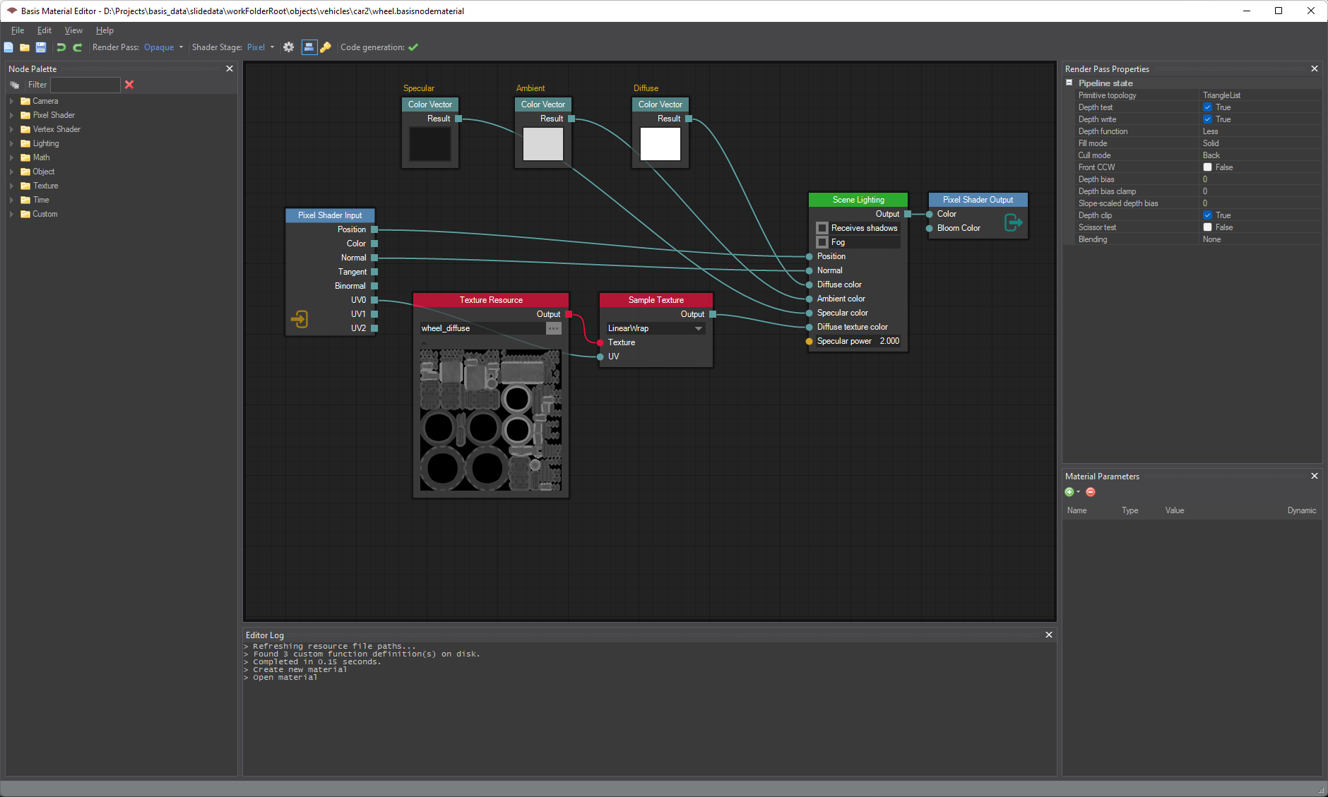
But why did I go with a visual editor? All of the requirements listed in the previous section could have been met by a textual system. Let’s list some of the reasons for going visual:
- Visual node editors seem to be the industry standard these days, which means it is the way of editing materials most people are familiar with.
- Creating a visual editor is not much more difficult than creating a (good) code-based editor.
- I am already using visual node-based scripting for mission logic, using a 3rd party editor. Having a framework for creating node graphs would be useful for that as well.
For the rest of this blog post, I will tell you how I went about creating the new material editor. As it turns out, creating one isn’t all that difficult if you carefully choose which parts to make yourself and which ones to use ready-made solutions for.
Selecting a UI framework
One of the first things to do when planning an application like a material editor is to decide on the programming language and UI framework to use. While the Basis game engine runtime is cross-platform, the tools and editors currently work only on Windows-based PCs. Most of the tools are written in C# using the Windows Forms (WinForms) toolkit as the UI framework. WinForms is quite an old framework at this point but it is very mature and stable. I decided to base the material editor on WinForms since it is the framework I have the most experience working with.
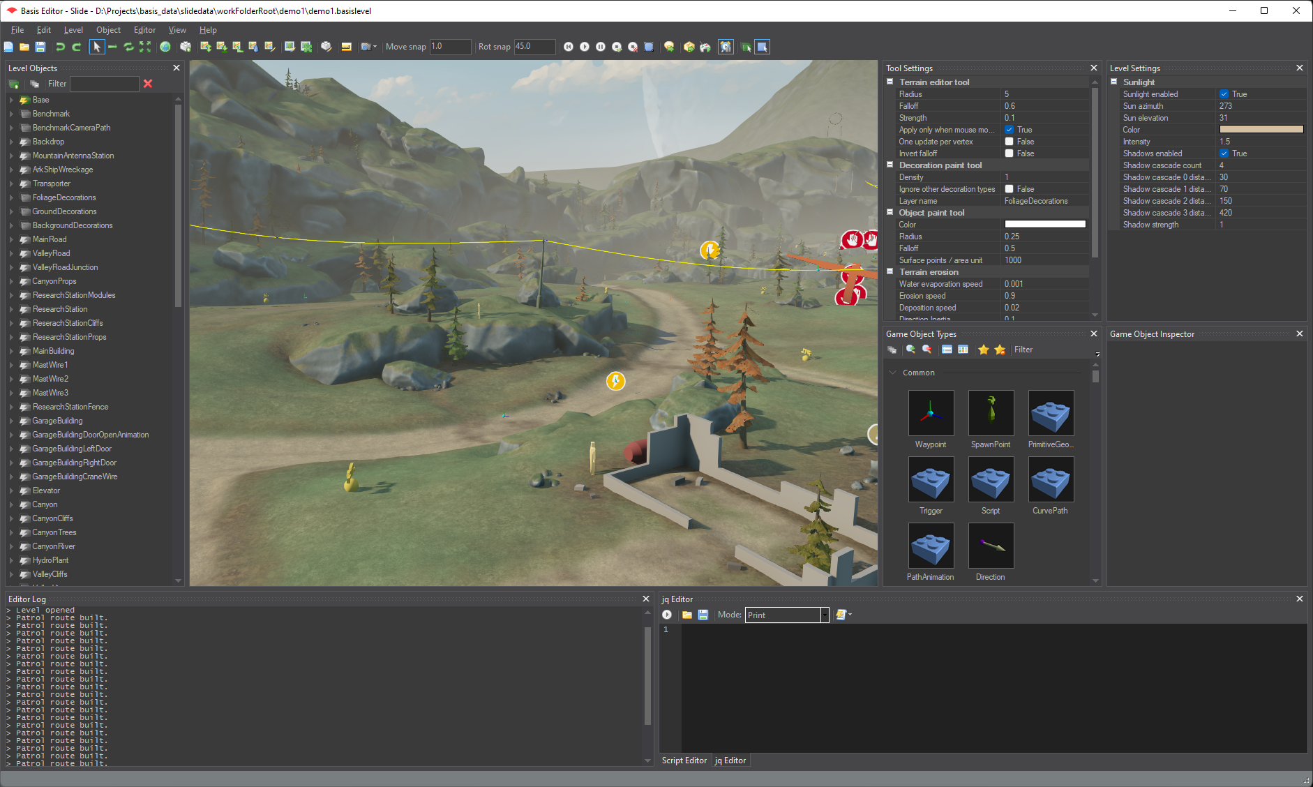
The Basis level editor is also written using C# and WinForms and uses a panel framework called DockPanel Suite to handle floating/docked tool windows. See image 3 below for a screenshot of the level editor. There are a lot of similarities between the UI of the material editor and the UI of the level editor.
My plans are to rewrite my editors using Avalonia or something similar after the game has shipped, which would also allow me to make them cross-platform. Keeping that in mind, it makes sense to separate the business logic from the UI logic as much as possible so that only the UI parts have to be rewritten later on.
STNodeEditor
Next, I started looking for a node editor framework/library to use. I could have written one from scratch but that would have set my schedule back by a month or so. Which ready-made framework to use obviously depends on the programming language and UI framework used. For WinForms, I found two frameworks that seemed to be feature-complete enough for my purposes, Node Editor Winforms and STNodeEditor.
After some testing I decided to go with STNodeEditor, in no small part because of its slick dark-themed looks. STNodeEditor has been a great asset during this project and I feel confident in stating that the material editor wouldn’t be as good as it is today without it. The library takes care of rendering the node graph, node selection, movement, adding and removing nodes and connections etc.
Editor command system
After integrating DockPanel Suite and STNodeEditor into the application it was time to start thinking about the code architecture for the editor. When creating an application like this, it can be tempting to start adding buttons and input handlers as you need them and directly modify the data whenever the user does anything. This, however, often leads to very messy, difficult to maintain, code. Especially if you want to separate the UI logic from the business logic you might want to think a bit harder about how to structure the application.
In order to curb my enthusiasm and keep from sprinkling data-modifying code everywhere I have a trick I have used with several of Basis’ editors; I force myself to support Undo/Redo. Almost every change to the material in the editor can be undone and redone. Having this requirement means you cannot simply poke at the data in a button handler. You need to think a bit more about how the program is structured.
One way to support undo/redo is to use a command system, where the UI simply creates a command and pushes it onto a list of commands to be executed. The commands are the only places in the code that are allowed to touch the material document data directly. Executing a command applies a delta to the data, and undoing that command applies the reverse delta. If you stick to this simple rule you will have no problem implementing a robust undo/redo system.
I should mention that the command system is not the only (nor necessarily the best) way to implement undo/redo systems. As with WinForms, it is simply the one I have the most experience working with.
As an example, the code listing below shows the code for the command which is run whenever a property of a shader node is changed. The “UI Node” is given as a parameter, along with the name of the property and the values before/after the change. All changes in the editor are initiated by the user, and the UI Node represents the node shown in the graph on the screen, ie. the node hosted by the STNodeEditor control.
public class SetShaderGraphNodePropertyCommand : MaterialEditorCommand
{
    public SetShaderGraphNodePropertyCommand(ShaderGraphNodeBase uiNode,
        string propertyName, object prevValue, object newValue)
    {
        mUINode = uiNode;
        Debug.Assert(mUINode != null);

        mDataNode = mUINode.MaterialNode;
        Debug.Assert(mDataNode != null);

        mPropertyName = propertyName;
        mPrevValue = prevValue;
        mNewValue = newValue;

        mNodeGraph = MaterialEditorApp.Instance.Document.CurrentNodeGraph;

        mUINodeEditor = (ShaderNodeEditor)mUINode.Owner;
    }

    public override string Name
    {
        get { return "Set shader graph node property"; }
    }

    public override bool Undoable
    {
        get { return true; }
    }

    public override bool CanExecute
    {
        get { return MaterialEditorApp.Instance.AcceptsInput; }
    }

    public override void Execute(bool redoing)
    {
        if (redoing)
        {
            PropertyInfo pi = mUINode.GetType().GetProperty(mPropertyName);
            pi.SetValue(mUINode, mNewValue);
        }

        {
            PropertyInfo pi = mDataNode.GetType().GetProperty(mPropertyName);
            pi.SetValue(mDataNode, mNewValue);
        }

        SetUnsavedChanges();
    }

    public override void Undo()
    {
        {
            PropertyInfo pi = mUINode.GetType().GetProperty(mPropertyName);
            pi.SetValue(mUINode, mPrevValue);
        }

        {
            PropertyInfo pi = mDataNode.GetType().GetProperty(mPropertyName);
            pi.SetValue(mDataNode, mPrevValue);
        }

        RestoreUnsavedChanges();
    }

    // ======================================

    private NodeGraph mNodeGraph;
    private ShaderNodeEditor mUINodeEditor;

    ShaderGraphNodeBase mUINode;
    MaterialNodeBase mDataNode;
    string mPropertyName;
    object mPrevValue;
    object mNewValue;
}
The data node, represented by mDataNode in the command above, is where the node data actually is stored. This node is completely unaware of the UI node or the STNodeEditor control. The UI node simply attaches itself to the data node and modifies its properties through reflection. This way the material library responsible for verifying the shader node graph and generating the shader code can be used without the UI. Indeed, it is very possible, and quite easy, to create a shader node graph completely through code.
From node editor to shader editor
Even though the application is called the “material editor”, it is 90% about creating and editing shaders. The remaining 10% is about packaging those shaders together with some data in such a way that the output can be used as a material. In other words, more than anything, the material editor is a shader editor. But having an editor where nodes can be connected together to form graphs doesn’t mean you have a shader editor. A true shader editor needs more knowledge about shaders and how data flows from one stage to the next.
Material render passes
Every material in the Basis game engine has one or more render passes enabled. For example, most objects use the Opaque and ShadowMap passes + one or more AO (ambient occlusion) passes. Having these passes enabled means that the object is rendered to the screen without any transparency, that it casts shadows onto other objects, and that it can participate in the AO calculations. Every render pass has its own shader program and each shader program is split into stages. The material editor lists the Vertex, Hull, Domain, Geometry and Pixel shader stages, although at the time of writing only the Vertex and Pixel shader stages are used by any real materials in the game. These are also the only stages (in addition to the Compute stage) supported by some graphics backends, such as Metal. In addition to one shader graph per enabled stage, the material editor allows the user to set up pipeline state separately for each render pass. The pipeline state settings include cull and fill mode settings, depth and blend settings etc.
Shader graph data flow
The next thing to tackle to make the editor more shader-aware is to define how the data flows through each shader graph. The nodes in the editor are split into three groups; input nodes, output nodes and regular nodes. Each shader graph must have one (and only one) output node. This is to unambiguously declare a target for the data. It also helps with stripping unreachable nodes from the code generation (more about that later). Each shader graph can also have (at most) one input node, but it is not always required. Eg. a pixel shader which writes the color ‘Red’ to each pixel can simply be a Color Vector node connected to an output node. If a graph has more or less than one output node or more than one input node, it is considered invalid by the material system, and by extension, the editor. Finally, each node type has a list of shader stages they are considered to be valid for. Eg. you cannot put a vertex shader output node in a pixel shader.
Node material serialization
Now that our editor knows a little more about materials and shaders it is time to start thinking about how to store materials on disk. The runtime material format is a custom binary format which has been in use for a long time. The only change required by the new node-based materials is that while the materials previously contained a resource reference (eg. the “basis/shaders/mesh_diffuse.binshader” path we looked at earlier) to the shader program, the new material files can now contain embedded runtime shader programs.
A binary format is useful for runtime use as it is compact and efficient, but it is probably not the best candidate for the material document files created and opened by the material editor. The data stored in these documents is fairly small and it makes sense to store them in a human-readable format, which can easily be opened with a text editor. It makes them easier to search through as well as make changes to if needed.
The STNodeEditor library has the ability to save a node graph to disk as well as load it back, but it uses a custom binary format. Additionally, as we already talked about previously, the STNodeEditor control doesn’t actually store any data. It merely displays the data found in the data nodes and allows the user to modify that data.
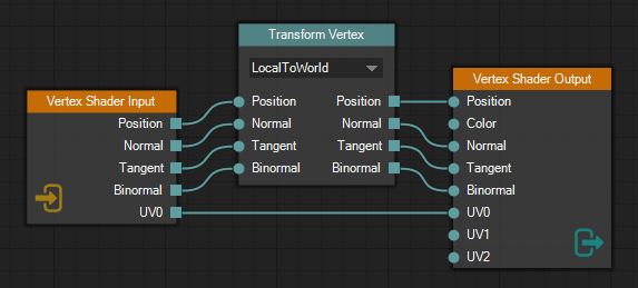
As with the old material system, I decided to store the material documents in JSON. When loading a material into the editor, the application first creates the data node graphs for each render pass and shader stage from the JSON data, and then populates the STNodeEditor with whichever node graph is active in the UI. Have a look at image 4 above. It shows the node graph for a standard vertex shader. The JSON data for the node graph can be seen below.
{
  "ShaderType": "Vertex",
  "ShaderGraph": {
    "NodeIDAccumulator": 3,
    "Nodes": [
      {
        "ID": 0,
        "NodeTypeName": "BasisMaterialLib.VSInputNode",
        "AssemblyQualifiedName": "BasisMaterialLib.VSInputNode, BasisMaterialLib, Version=1.0.0.0, ...",
        "Left": 176,
        "Top": 158,
        "Width": 134,
        "Height": 120,
        "Comment": ""
      },
      {
        "ID": 1,
        "NodeTypeName": "BasisMaterialLib.VSOutputNode",
        "AssemblyQualifiedName": "BasisMaterialLib.VSOutputNode, BasisMaterialLib, Version=1.0.0.0, ...",
        "Left": 559,
        "Top": 138,
        "Width": 142,
        "Height": 180,
        "Comment": ""
      },
      {
        "ID": 2,
        "NodeTypeName": "BasisMaterialLib.TransformVertexNode",
        "AssemblyQualifiedName": "BasisMaterialLib.TransformVertexNode, BasisMaterialLib, Version=1.0.0.0, ...",
        "Left": 366,
        "Top": 98,
        "Width": 140,
        "Height": 145,
        "Transform": 0,
        "Comment": ""
      }
    ],
    "Connections": [
      {
        "FromNodeID": 0,
        "FromPinName": "Position",
        "ToNodeID": 2,
        "ToPinName": "Position"
      },
      {
        "FromNodeID": 0,
        "FromPinName": "Normal",
        "ToNodeID": 2,
        "ToPinName": "Normal"
      },
      {
        "FromNodeID": 0,
        "FromPinName": "Tangent",
        "ToNodeID": 2,
        "ToPinName": "Tangent"
      },
      {
        "FromNodeID": 0,
        "FromPinName": "Binormal",
        "ToNodeID": 2,
        "ToPinName": "Binormal"
      },
      {
        "FromNodeID": 0,
        "FromPinName": "UV0",
        "ToNodeID": 1,
        "ToPinName": "UV0"
      },
      {
        "FromNodeID": 2,
        "FromPinName": "Binormal",
        "ToNodeID": 1,
        "ToPinName": "Binormal"
      },
      {
        "FromNodeID": 2,
        "FromPinName": "Normal",
        "ToNodeID": 1,
        "ToPinName": "Normal"
      },
      {
        "FromNodeID": 2,
        "FromPinName": "Position",
        "ToNodeID": 1,
        "ToPinName": "Position"
      },
      {
        "FromNodeID": 2,
        "FromPinName": "Tangent",
        "ToNodeID": 1,
        "ToPinName": "Tangent"
      }
    ]
  }
}
As you can see, the data is quite easy to read. Also, it can be read by any program with a JSON parser and it doesn’t depend on any 3rd-party libraries such as STNodeEditor. Finally, it is easy to search through. Eg. if you wanted to know whether or not a node of a certain type is used, you can use the ‘find in folder’ functionality of your favorite text editor and quickly search through all of the materials in the whole project.
Shader code generation
Generating shader code based on the node graphs was one of the tricker parts of the project, but perhaps not as difficult as I initially feared. I came up with a quite flexible and powerful system of generating vertex and pixel shader code. Code generation for the other shader stages hasn’t been implemented yet, but I don’t expect any big problems with them either.
Before you can generate any code from a node graph you have to make sure the graph makes sense, from a shader’s point of view. We briefly touched on the subject of shader node graph validation already, when we talked about input and output nodes. As a quick recap, the first checks done on all graphs is to make sure the graph has one (and only one) output node, at most one input node, and that all nodes in the graph are valid for the current shader stage. If any of these checks fail, the code generation stops and displays an error to the user.
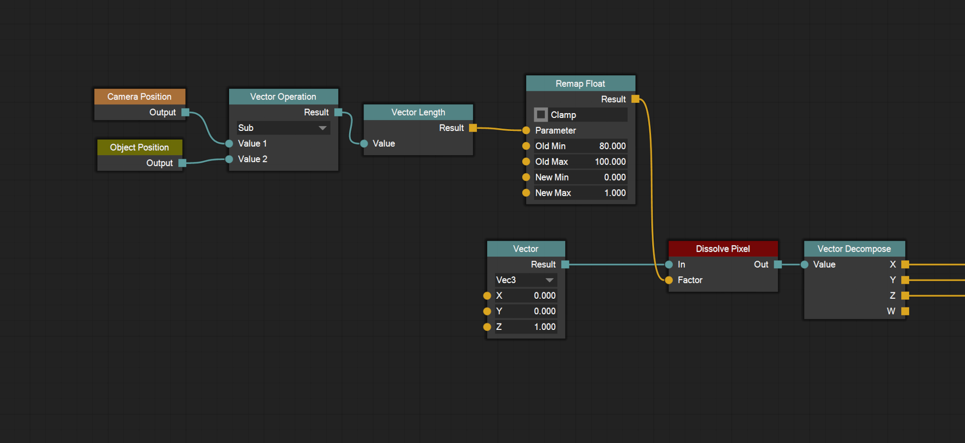
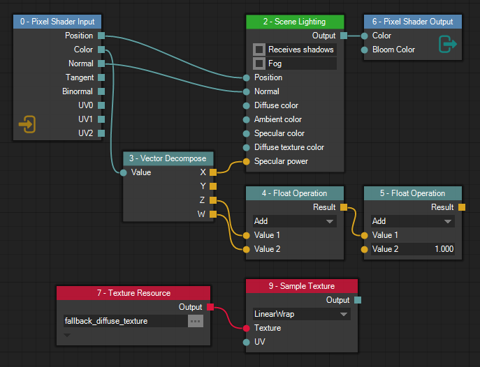
The next step is to eliminate unused/unreachable nodes. Consider the pixel shader node graph in image 5. It is a valid pixel shader since it contains one input node and one output node. However, only four of the nodes in the graph actually contribute to the final pixel value.
To exclude the unreachable nodes from the code generation process we start at the output node and move backwards through the node graph. We follow every connected input pin of the current node and keep a list of all nodes encountered until we have run out of input pins to follow.
In the case of the graph in image 5 we would start at the Pixel Shader Output node. We would then move to the Scene Lighting node and then either the Vector Decompose node or the Pixel Shader Input node. Note that we never visit the Float Operation nodes since we only move backwards (from input pin to output pin) during the exclusion process. We also don’t visit the Texture nodes since they aren’t connected to the output node at all. The unreachable nodes aren’t removed from the material document itself, but they are excluded from any further code generation. This way, the user can temporarily disconnect a branch of the node graph, and still be able to reconnect it later if they want.
Once we have determined which nodes are to be included in the code generation we have to verify that all inputs to those nodes are satisfied. What this means is up to each and every node type to determine. Eg. the Scene Lighting node in image 5 requires the Position input pin to be connected (since it cannot calculate the lighting without knowing the position), but not all of the color input pins need to be connected. If any of the nodes report that their inputs aren’t satisfied, the code generation process is stopped and an error is displayed.
The last piece of validation we need to do is make sure there are no cycles in the node graph. In other words, the graph needs to be a directed acyclic graph. The editor doesn’t currently allow cyclic connections to be made at all, so we don’t need to do any further checking at this point.
Node evaluation order
Next, we need to determine the node evaluation order of the graph. This is the order in which the operations defined by the nodes are to be executed so that all data dependencies are met and the desired output can be calculated. For a human, it is quite obvious that the Vector Decompose node in image 5 must be evaluated before the Scene Lighting node, but a computer needs some kind of algorithm to determine this. Luckily for us, there are algorithms available for exactly this purpose. The one I ended up using is Kahn’s algorithm which is quite easy to implement. It is worth noting that there might be several valid node evaluation orders for a given graph, and Kahn’s algorithm gives us one of them.
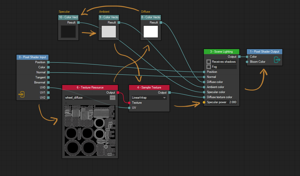
Consider the node graph in image 6. A developer flag has been enabled which shows the nodes’ IDs in their title bars. Kahn’s algorithm gives us one possible node evaluation order as: 0, 6, 8, 10, 9, 4, 3, 1, where each number is a node ID, and I drew the orange arrows on top to help visualize the order. We start at node 0, the input node on the left, then evaluate the texture resource node with ID 6, then the diffuse color node with ID 8 etc. This is an example of a graph with many possible node evaluation orders. Eg. the specular, ambient and diffuse color nodes can be evaluated in any order as long as they are evaluated before the scene lighting node.
Finally, some code
Let’s now have a look at the code generated for the pixel shader in image 6. The code is generated with the “verbose” flag enabled, which add lots of comments to the code, explaining what goes where:
PixelData __BasisGeneratedPS(VertexOut ps_in)
{
    // Node eval order: 0, 6, 8, 10, 9, 4, 3, 1

    // == Preamble ==

    // == Main body ==

    // BEGIN PSInputNode, ID: 0
    float3 _ps_local_0 = ps_in.position;
    float3 _ps_local_1 = normalize(ps_in.normal);
    float2 _ps_local_2 = ps_in.uv0;
    // END PSInputNode, ID: 0

    // BEGIN TextureResourceNode, ID: 6
    // END TextureResourceNode, ID: 6

    // BEGIN ColorVectorNode, ID: 8, Comment: Diffuse
    float4 _ps_local_3 = float4(1.00000f, 1.00000f, 1.00000f, 1.00000f);
    // END ColorVectorNode, ID: 8, Comment: Diffuse

    // BEGIN ColorVectorNode, ID: 10, Comment: Specular
    float4 _ps_local_4 = float4(0.00807f, 0.00807f, 0.00807f, 1.00000f);
    // END ColorVectorNode, ID: 10, Comment: Specular

    // BEGIN ColorVectorNode, ID: 9, Comment: Ambient
    float4 _ps_local_5 = float4(0.68563f, 0.68563f, 0.68563f, 1.00000f);
    // END ColorVectorNode, ID: 9, Comment: Ambient

    // BEGIN SampleTextureNode, ID: 4
    float4 _ps_local_6 = gNodeGraphTexture0.Sample(gNodeGraphTextureSampler0, _ps_local_2);
    // END SampleTextureNode, ID: 4

    // BEGIN SceneLightingNode, ID: 3
    float4 _ps_local_7;
    {
    #if BASIS_SSAO_ENABLED == 1
        float4 ssaoPos = ps_in.ssaoPosition;
    #else
        float4 ssaoPos = float4(0.0f, 0.0f, 0.0f, 0.0f);
    #endif
        float4 globalAmbient = float4(calculateGlobalAmbient(float4(_ps_local_1.xyz, 1.0f)).rgb, 1.0f);
        _ps_local_7 = sceneLighting(_ps_local_0, _ps_local_1, _ps_local_3, _ps_local_5, globalAmbient,
            _ps_local_4, _ps_local_6, 2.000f, ssaoPos, true, true);
    }
    // END SceneLightingNode, ID: 3

    // BEGIN PSOutputNode, ID: 1
    return calculatePixelData(_ps_local_7);
    // END PSOutputNode, ID: 1
}
First, the code generator writes the node evaluation order as a comment. You can also clearly see where each node begins and ends thanks to the BEGIN and END comments, courtesy of the verbose flag. Notice how the shader consists of two parts, the preamble (which is empty here) and the main body in which every node gets to insert code. Also, notice how the Texture Resource node with ID 6 actually doesn’t generate any code, but thanks to the verbose flag you can still see the place in which it was evaluated.
Looking at the generated code, it should be quite obvious how node connections are implemented in code. Almost all nodes declare and write to local variables. Subsequent nodes can then read the values of previously declared local variables. The variable names are automatically generated by the code generator. This is to prevent name clashes between two nodes in the same shader body. Certain nodes, such as the Scene Lighting node in the code above, create their own scopes and declare temporary variables there. The Scene Lighting node above declares two such variables, ‘ssaoPos’ and ‘globalAmbient’. They won’t cause naming clashes as long as they are properly scoped.
Let’s now look at the vertex shader for the same material. We have actually already seen the node graph for the vertex shader, in image 4, but it is shown again in image 7 for your viewing pleasure. This is the standard way of declaring a vertex shader using the editor, although for this particular material it is a bit overkill since it transforms the tangent and binormal even though the pixel shader doesn’t use them. Let’s have a look at the code generated from this shader node graph:
VertexOut __BasisGeneratedVS(VertexIn vs_in, uint instanceID : SV_InstanceID)
{
    // Node eval order: 0, 2, 1

    // == Preamble ==

    // Snippet InstanceData:
    uint pmst_instanceIndex = instanceID + gFirstInstanceIndex;
    RenderInstanceData pmst_instanceData = __BasisInstanceData[pmst_instanceIndex];

    // Snippet MatrixViewProjection:
    float4x4 pmst_viewProjMatrix = mul(gCameraProjection, gCameraView);

    // == Main body ==

    // BEGIN VSInputNode, ID: 0
    float3 _vs_local_0 = vs_in.position;
    float3 _vs_local_1 = vs_in.normal;
    float3 _vs_local_2 = vs_in.tangent;
    float3 _vs_local_3 = vs_in.binormal;
    float2 _vs_local_4 = vs_in.uv0;
    // END VSInputNode, ID: 0

    // BEGIN TransformVertexNode, ID: 2
    float3 _vs_local_5;
    float3 _vs_local_6;
    float3 _vs_local_7;
    float3 _vs_local_8;
    {
        float3x3 rotation = (float3x3)pmst_instanceData.world;
        _vs_local_5 = mul(pmst_instanceData.world, float4(_vs_local_0, 1.0f)).xyz;
        _vs_local_6 = mul(rotation, _vs_local_1);
        _vs_local_7 = mul(rotation, _vs_local_2);
        _vs_local_8 = mul(rotation, _vs_local_3);
    }
    // END TransformVertexNode, ID: 2

    // BEGIN VSOutputNode, ID: 1
    VertexOut vs_out;
    vs_out.position = _vs_local_5;
    vs_out.sv_position = mul(pmst_viewProjMatrix, float4(_vs_local_5, 1.0f));
    vs_out.normal = _vs_local_6;
    vs_out.tangent = _vs_local_7;
    vs_out.binormal = _vs_local_8;
    vs_out.uv0 = _vs_local_4;

    #ifdef BASIS_CLIP_POSITION_IN_VERTEX_OUT
    vs_out.clipPosition = vs_out.sv_position;
    #endif

    #if BASIS_SSAO_ENABLED == 1
    vs_out.ssaoPosition = mul(gCameraViewProjTex, float4(vs_out.position, 1.0f));
    #endif

    #ifdef BASIS_ENABLE_CUSTOM_CLIPPING_PLANES
    vs_out.customClipDistance = dot(float4(vs_out.position, 1.0f), gCustomClippingPlane);
    #endif

    #ifdef BASIS_INSTANCE_INDEX_IN_VERTEX_OUT
    vs_out.instanceIndex = pmst_instanceIndex;
    #endif

    return vs_out;
    // END VSOutputNode, ID: 1
}
We have a few things of note here. This node graph has only one valid node evaluation order: The input node, the Transform Vertex node, and the output node. This time we also have some code in the preamble part of the shader. Something has added two “preamble snippets” before the first actual node.
Sometimes nodes require some auxiliary data to carry out their task, and quite often that data is required by several nodes. It would be wasteful to recalculate the same data over and over as part of the nodes’ own code when it can be calculated once and then reused by multiple nodes. This is the idea behind preamble snippets.
In the case above, the Transform Vertex has requested the ‘InstanceData’ snippet as it needs to read the world matrix of the object instance being rendered. Similarily, the output node has requested the ‘InstanceData’ and ‘MatrixViewProjection’ snippets. In this case, we don’t save many cycles by using snippets, but if another node would want to use the view-projection matrix for something, we would already save one matrix multiplication. Data exposed through preamble snippets are declared using well-known local data variables prefixed with ‘pmst_’.
A few more bits
We have covered the majority of the code generation system, but there are a few more details to it. In addition to requesting preamble snippets and inserting code into the shader body, all nodes can:
- Include shader headers
- #define symbols
- Associate local variables with output pins
- Declare textures and texture samplers in the global scope
- Affect parts of the shader function signatures, such as return type and parameters
- Set misc global shader generation flags
- Query their surroundings (eg. get local variable names and types associated with pins)
Some of the items might seem obvious. Of course the nodes can #define symbols since they can input arbitrary code into the shader body, right? That is true, but that would put the #define right in middle of the shader body. Typically, nodes want their #defines to appear at the very top, even before standard headers are included, and so the shader generator exposes functionality to do this.
Not all flags and functions are mutually compatible. Eg. if one node wants to make the pixel shader return void while another wants a float4, you’ll get an error. However, the code generation is very quick. All materials created so far have had their shader code generated in a few milliseconds, and the code gets generated in the background for every change in the editor, so the user gets immediate feedback if they try to do something wrong.
Putting the pieces together
We have now reached a point where we can generate valid source code for all shader programs in the material. The next thing we need to do is compile the code, which is done by writing the code to a temporary file on disk and passing it to the Basis game engine’s standard shader compiler. If the compilation succeeds, the output is written to another temporary file which is read back into memory. The runtime shader data is then inserted into the material file along with the pipeline state and other data needed by the render pass. The shader compiler has not been modified at all to support the new node-based materials. In fact, it has no idea if the shader it is compiling is an old-style handwritten shader or a generated shader produced by the new material editor.
It is worth mentioning that the old way of authoring shaders is not going to go away just because we can generate material shaders. There are lots of shaders in the game engine that are considered to be “lower level” shaders, ie. shaders that are part of the renderer itself as opposed to any material. These will continue to be hand written.
Material parameters
Congratulations, you can now generate shaders and use them to put together materials. Life is grand! Or is it? In my case, I quickly realized that working with node graphs is a fair bit slower than working with a text-based system if you have to find and replace values in your materials.
Consider the following example. You have a material for the leaves of a tree. We animate the tree branches using a simple wind animation node in the vertex shader. The wind strength is a floating point value which needs some tweaking to get right. Now consider you have 5 slight variations of the same tree, each requiring their own material. Each material has 4 render passes, each with their own vertex shader. Now, if you wanted to change the wind strength for all the trees you would have to do it in 5 * 4 = 20 different places spread out over multiple files. It is easy to miss one place which might lead to the shadows of a tree not matching the tree itself, or something even worse.
I was clear to me that I would need some kind of system to make changes like these easier to make, and material parameters was the solution I came up with. Material parameters are data types shared among all render passes and shader stages of a material. Eg. rather than having the wind strength hard coded into every shader node graph you can create a material parameter of type float and give it the name “WindStrength.” You can then create a Float Parameter node which reads the value of the parameter and exposes it to the rest of the node graph.
Some of you may have noticed those checkboxes in the column called “Dynamic”. Those are currently disabled since the node-based materials don’t support runtime modifications yet, but my plan is for the material parameters marked as dynamic to be placed in a generated constant buffer. That way material parameters such as floats and vectors could be updated at runtime.
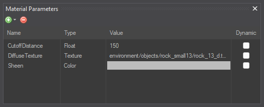
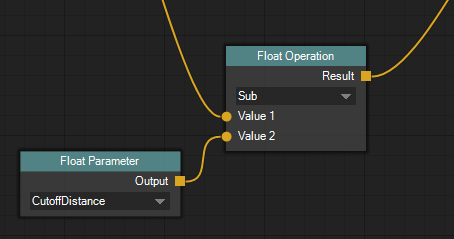
In image 9 a float material parameter named “CutoffDistance” is read and subtracted from another float value. The Float Parameter node knows which parameters have been declared and displays a drop-down list of the ones with the correct type.
Let’s get back to the wind strength example. We have made our lives a little easier since we no longer have to change the value in every render pass and shader stage. We can simply adjust the material parameter value and all uses of it within the same material are updated.
But what about those 5 variations of the same tree? You still have to open every material and change the value. We can do better! This is where material variants come into play.
Material variants
Material variants allow the user to create a slight variation of another material, as long as the base material has one or more material parameters. The only things the material variant is allowed to change are the material parameter values. Because of this, it is important to expose values as material parameters if you think a variant might want to change them later. For static (as in, not dynamic) material parameters there is no runtime overhead since the values are still hardcoded into the shader code.
In our example with the 5 tree variants, the user can adjust certain parameters while leaving the wind strength parameter unchanged. This way, if the wind strength is changed in the base material later on, all the material variants will have their values updated as well. We have reduced the number of places where the user needs to change the wind strength from 20 to 1. Nice!
Creating nodes
The last thing I want to cover in this blog post is how shader nodes are created. When creating a new node type you have to choose between making it a built-in node or a custom function node.
Built-in nodes
Built-in nodes are created completely in C# code. They are typically very general-purpose, eg. all math nodes are built-in nodes. They can store state, such as vector values, the selected index in a drop-down menu or a texture resource path. Since they are created in code, their UI can also be very complex. Eg. they can dynamically add/remove pins, show resource previews etc. Built-in nodes are the backbone of the whole node graph shader system, but they have some drawbacks. To create one, you need to modify the material system code and rebuild the material editor and converter. You also need to create two C# classes for each node type, the UI version and the data version. Let’s have a look at the code for a relatively simple built-in node, the Float node. Here is the data side:
namespace BasisMaterialLib
{
    [ValidForShaderStage(ShaderTypes.ShaderStage.All)]
    public class FloatNode : MaterialNodeBase
    {
        public FloatNode() : base(MaterialNodeType.Regular)
        {
            mOutputPin = AddOutputPin(new NodePin("Result", typeof(float), false));
        }

        [SerializedNodeData]
        [MaterialNodeData]
        public float Value { get; set; } = 0.0f;

        // ======================================

        public override string[] GenerateCode(ShaderGraphCodeGenerationContext ctxt)
        {
            List<string> lines = new List<string>();

            string value = TypeConversions.GetHLSLLiteral(Value);

            ShaderGraphCodeGenerationContext.Local lcl = ctxt.DeclareLocal(TypeInfo.TypeID.BASIS_TYPE_FLOAT);

            lines.Add(string.Format("float {0} = {1};", lcl.symbolName, value));
            ctxt.RegisterOutputPinSymbolName(mOutputPin, lcl.symbolName);

            return lines.ToArray();
        }

        // ======================================

        private NodePin mOutputPin;
    }
}
As you can see, the node class has some state; a Value property annotated with the SerializedNodeData attribute. This makes the material library save/load that value in the material document file. The property also has the MaterialNodeData attribute which we will get to in a bit. The most interesting part of the class is the GenerateCode() method which returns a list of source code lines to insert into the shader body. The ShaderGraphCodeGenerationContext object is the entry point to the code generation system and contains methods for performing most code generation tasks. The Float node uses it to declare a new local variable and registers it as the data storage for its output pin, so subsequent nodes know where to look for the float data produced by the node. Now let’s look at the UI side of the same node type:
namespace BasisMaterialEditor
{
    [BuiltInMaterialNode("/Math/Float/", "Float", "Creates a float with the given value.")]
    public class FloatNode : ShaderGraphNodeBase
    {
        public FloatNode() : base("Float",
            ShaderNodeGraphColors.NodeCategory_Math,
            BasisMaterialLib.MaterialNodeBase.MaterialNodeType.Regular)
        {
            this.AutoSize = false;
            this.Size = new Size(100, 65);

            this.OutputOptions.Add("Result", typeof(float), false);

            mValueInputBox = new STNodeInputBox(this, "Value", typeof(float));
            mValueInputBox.DisplayRectangle = new Rectangle(10, 21, 80, 18);
            this.Controls.Add(mValueInputBox);
        }

        // ======================================

        [MaterialNodeData]
        public float Value
        {
            get { return mValue; }
            set { SetField(ref mValue, value, "Value"); }
        }

        // ======================================

        private float mValue = 0.0f;

        STNodeInputBox mValueInputBox;
    }
}
As you can see, the class has the same name as the data class, but it sits in another namespace (and indeed, in another assembly). It has the same Value property annotated by the MaterialNodeData attribute. This attribute is used to connect the data values of the two classes. Remember, the UI class is created only in the material editor as a visual interface to the data class, and needs to know which data members it can modify.
The UI class also has an STNodeInputBox member which is the text box the user can enter the value into. It is given the name of the property to modify and uses reflection to do the actual modification. The SetField() method called in the property setter belongs to the node base class and needs to be called when a property is set to make sure the correct editor command is executed. Remember, only editor commands are allowed to directly touch the data.
You might wonder why I have the system set up like this? Why do I need two classes to represent the node? It makes a bit more sense when considering that the data side is only concerned with holding onto the data and generating the shader code, while the UI side is only concerned with presenting the data and allowing the user to modify it. A node-based material can be converted into its runtime form using a command line converter which never creates the UI node class, only the data node class.
There is a bit of code duplication found here which I could perhaps get rid of. Eg. The UI side could automatically generate its input/output pins based on what is available on the data side. But then again, the current system allows the UI nodes to freely modify their UI at runtime. Eg. The vector node which typically has four input pins (for a 4D vector) can hide the Z and W pins when creating a 2D vector, even though the data side stays the same.
We have covered built-in nodes. What about the other type, custom function nodes?
Custom function nodes
Sometimes you have a game-specific piece of shader code and you want to encapsulate it into a node for use in a node-based material. Maybe this is some very experimental thing you are working on and you aren’t exactly sure it is going to work out. Or maybe you have a piece of shader code which is only really useful in a certain game.
In these kinds of situations it is unfortunate to have to create built-in nodes to encapsulate your shader code. Not only is iteration quite slow as you have to keep rebuilding the material editor after every change, but you also “pollute” the game engine library of general-purpose nodes with your game-specific, potentially expermiental, node types.
Custom function nodes are designed for these situations. A custom function node is defined in a text file which is read by the material system and can thus be modified very quickly. In addition, custom function files can be stored in the game data files, separately from the game engine files. The custom function system is partially inspired by a blog post by Niklas Andersson, in which he describes a similar system.
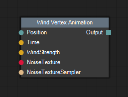
Image 10 shows the Wind Vertex Animation node which is a custom function node. It has input pins and an output pin, but nothing else. The custom function system currently doesn’t allow nodes to have any state or custom UI. They simply act as a way to hook arbitrary code into a node graph, by exposing a number of input/output pins. Let’s have a look at the custom function definition file for the node:
//!NodeTitle: Wind Vertex Animation
//!NodePath: /Custom/Wind/
//!NodeDescription: Animates a vertex position using the wind system.
//!NodeValidIn: Vertex
//!InputPins: Position: float3, Time: float, WindStrength: float, NoiseTexture: Texture2D, TextureSampler: sampler
//!OutputPins: Output: float3

//!ShaderCodeGenFlags: VertexIDInVSSignature
//!ShaderPreambleSnippets: None

//!Include: "../game/shaders/wind_simulation.h"

// $ denotes an output pin, % an input pin
float3 $Output = simpleWindGetPosWS(%Position, vertexID, %Time, %WindStrength, %NoiseTexture, %TextureSampler);
The lines beginning with “//!” are instructions to the custom function system and describe some aspect of the node. The node declares its pins and can request preamble snippets, include custom headers etc. The Wind Vertex Animation node also sets a global code generation flag ‘VertexIDInVSSignature’ which causes the vertex shader to receive the current vertex ID as part of its parameters. All lines NOT beginning with “//!” are inserted into the shader body. Symbols prefixed with the dollar sign are treated as output pins while percent signs denote input pins. The code generation system then replaces those symbols with the correct symbol names during compilation. Here is an example of what that might look like:
// BEGIN CustomFunctionNode, ID: 3
float3 _vs_local_10 = simpleWindGetPosWS(_vs_local_7, vertexID, _vs_local_4, _vs_local_9,
    gNodeGraphTexture0, gNodeGraphTextureSampler0);
// END CustomFunctionNode, ID: 3
The code generated by the Wind Vertex Animation node is just a single line, ie. the call to simpleWindGetPosWS(). However, there is no limit on how long/complex that function, which comes from the included header file wind_simulation.h, is. This way, very complex code can be inserted into the shader while keeping the actual shader body short and clear. However, nothing prevents a custom function node from inserting all of its code directly in the shader body, preferably scoped to prevent naming clashes.
The custom function system partially breaks some of the rules I set for myself during the start of the project, particularily the bit about “not requiring the user to remember words or identifiers”. It is true that the person creating the node has to remember words like ‘VertexIDInVSSignature’, but new nodes aren’t created that often and USING the node is just a easy as intended. For node authors, some sort of cheat sheet should be created (and updated).
Things left to do
While the material editor is very usable in its current state there are lots of things left on my TODO list. The first one is the ability to update material parameters at runtime. As previously mentioned, this is going to be baked into the material parameter system. The runtime side already has support for updating constant buffers on the fly so the bulk of the work will be generating the constant buffer layout based on the dynamic material parameters.
Another thing briefly mentioned earlier is the ability to generate shader permutations. This should be mostly invisible to the user (except perhaps as a slightly longer export phase) so it shouldn’t require any changes to the actual editor application, but rather the material converter. Before I start on that though, I want to optimize the shader compiler to make the compilation process faster. Introducing shader permutations means compiling the same shader program many times using different flags, and I don’t want the export phase to be very long.
As mentioned previously, only vertex and pixel shaders actually generate code right now. Enabling code generation for the other stages should be relatively simple, but as I currently don’t have any materials using them I haven’t done that yet. The terrain system uses the tesselation stages and the particle renderer uses the geometry stage, however, those currently don’t use the standard materials but their own shaders. Maybe the material editor is a good reason to port those over to the standard material system.
I also have lots of quality-of-life improvements to make, things like being able to copy/paste parts of a shader graph, the ability to set export flags controlling things like shader debug symbols, optimization levels etc.
Conclusion
Overall, I am happy with the new material editor. I have created tools in the past I have immediately started to dislike and the material editor is not one of them, so that’s a good sign. While developing the editor I kept a video devlog on Youtube where I went through the new features as I was developing them. In some ways, the videos provide a more in-depth look at the project than this blog post, so be sure to check out the playlist if you are interested.
Thanks for reading! I hope this blog post has been interesting. I sure would have liked to read it when starting the project. Now I am pretty excited to get back to working on the game!